24 Hour Timer Circuit - Timing / Timer Electronic Tutorial
24 Hour Timer Circuit - Timing / Timer Electronic Tutorial
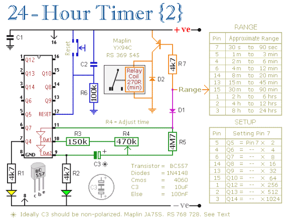
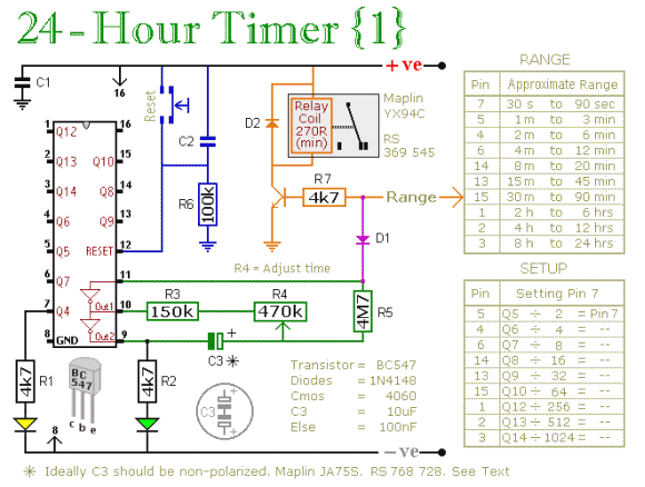
24 Hour Timer Circuit and Tutorial - A timer circuit with independent mark and space periods. A simple astable timer made with the 555, the mark (on) and space (off) values may be set independently. The timing chain consists of resistors Ra, Rb and capacitor Ct. The capacitor, Ct charges via Ra which is in series with the 1N4148 diode.
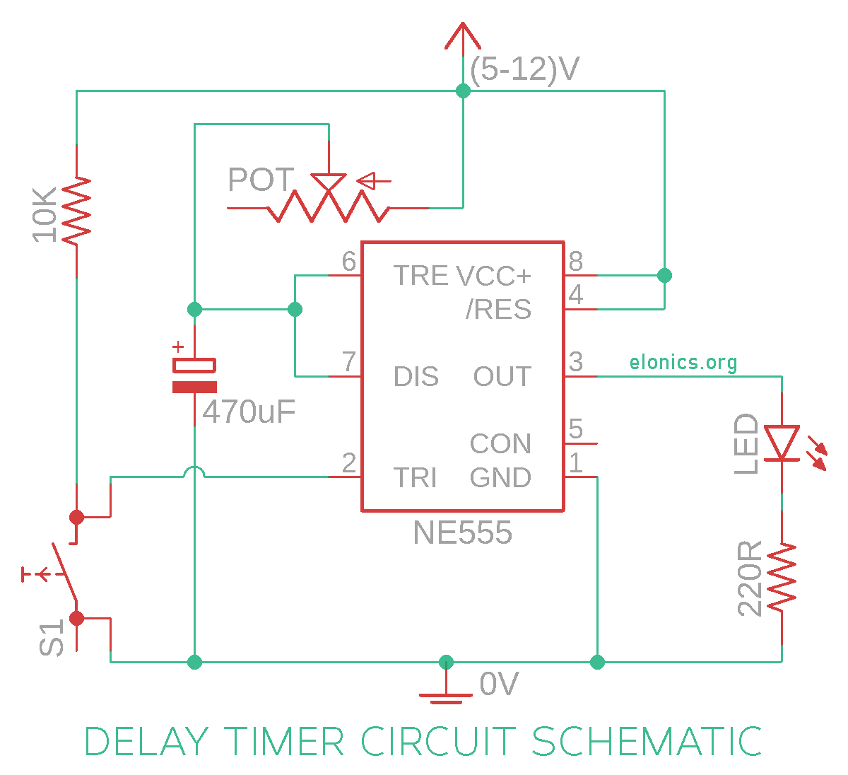
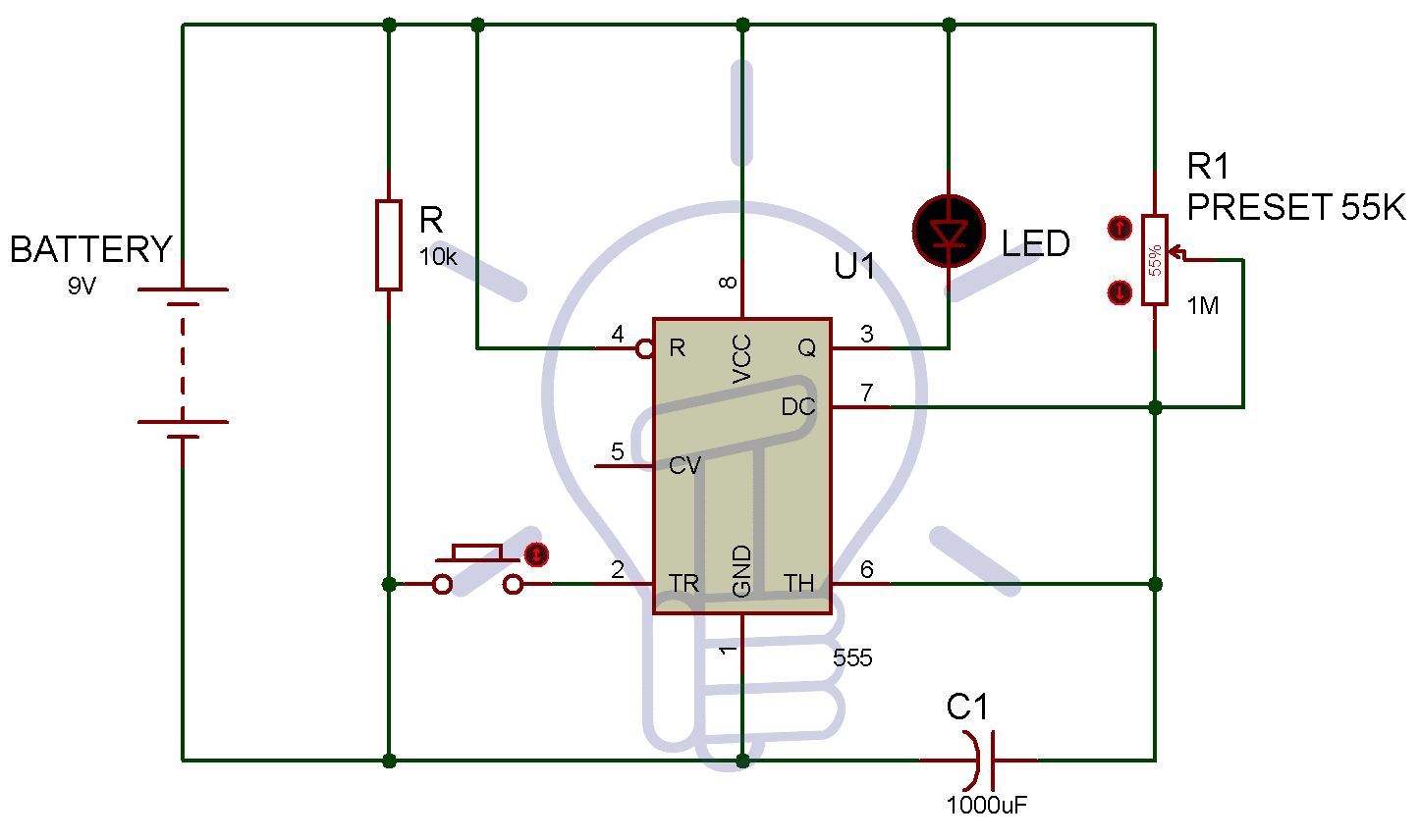
Adjustable Auto On Off Delay Timer Circuit Using 555 IC

555 Timer Tutorial - The Monostable Multivibrator

main 24-Hour 120V Electromechanical Panel Mount Timer Module with Manual Override, 15 Minute Intervals, 21A, SPDT

Make ON OFF Delay Timer circuit electronics diy project
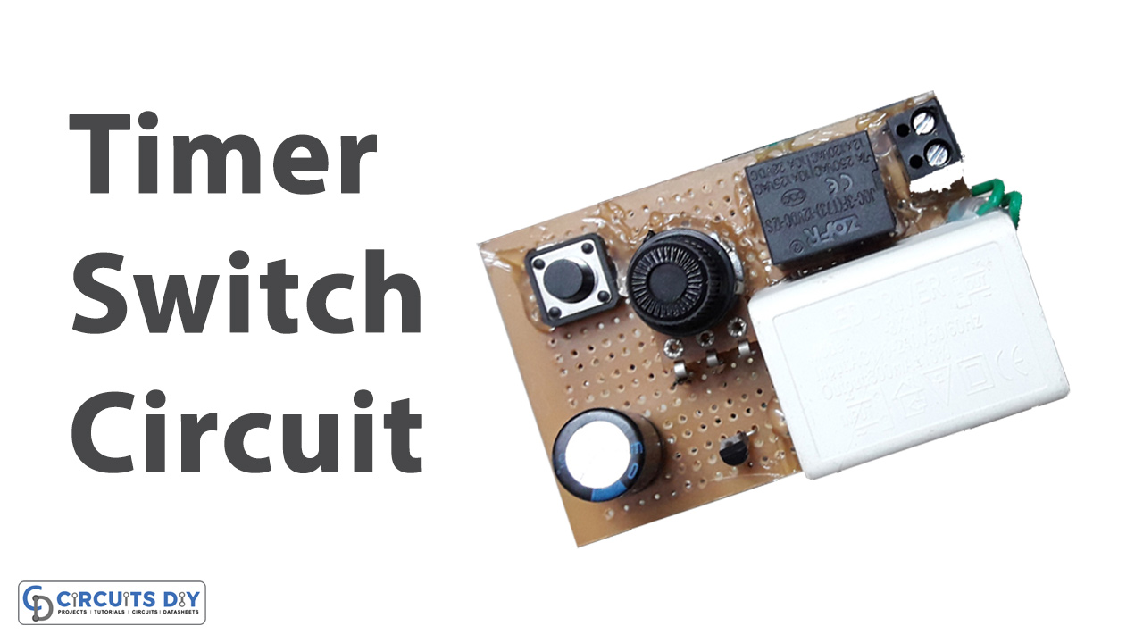
How to make a Timer Switch Using BC547 Transistor

mechanical 24 hour timer wiring diagram

24 Hour Timer Circuit - Timing / Timer Electronic Tutorial, Circuits, Schematics, Diagrams - Hobby Projects

24 Hour Digital Clock and Timer Circuit - Engineering Projects
24 Hour Timer Circuit - Timing / Timer Electronic Tutorial, Circuits, Schematics, Diagrams - Hobby Projects

How does a timing relay work?
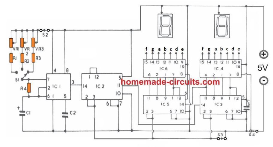
Simple Digital Timer Circuit with 2 Digit Display

GE 24-Hour Indoor Basic Outlet Timer, 1 Polarized Timer Outlet, Plug In Timer, Daily On/Off Cycle, 30 Minute Interval, for Lamps, Seasonal Appliances, & Portable Fans, Light Timer, 15119

555 Timer - 1. Introduction to 555 Timers - Electronics Tutorials
1 to 15 Minute Timer Circuit Diagram, Working and Applications
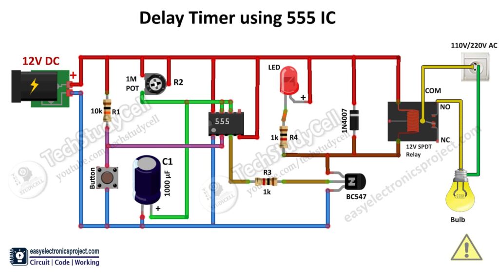
Time Delay Relay circuit using 555 timer IC - Electronics Projects

